Execute TLED upgrades without compromising advanced control solutions (MAGAZINE)
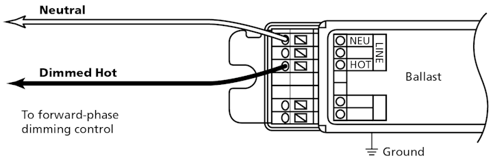
FIG.
1. The two-wire method provides simple control upgrades by using the
same existing wiring for non-dimmable ballasts. (All images courtesy of
Lutron Electronics.)
Starting in the mid-2010s, broad-based LED upgrades to fluorescent lighting fixtures focused primarily on saving energy in the space rather than on improving lighting quality. A common strategy of installing tubular LED upgrades (TLEDs) offered significant energy efficiencies and extended lamp life compared to traditional fluorescent lighting. TLEDs were alsoeasy to install, as they fit into existing fluorescent lamp sockets, and for day-to-day switched lighting they helped many buildings quickly meet energy reduction goals.
Now, facility managers are facing a new challenge — how to implement effective TLED retrofits in buildings
that have more sophisticated control systems and dimming ballasts. They want to upgrade the fixtures without compromising existing lighting quality and control functionality. This is especially relevant in spaces like Class A offices with installed fluorescent T8 and T5 lamps, high-performance dimming ballasts, smart control systems, and advanced
sequence of operations.
Directly replacing fluorescent bulbs with
TLEDs on high-performance dimming ballasts is not advisable. Experience
has shown that using traditional high-performance dimming ballasts with
new TLED lamps often results in mixed or poor performance due to the
bulbs’ different electrical characteristics. Problems like flicker,
uneven dimming, and undesirably bright low-end light levels are common.
Instead, when upgrading to TLEDs in architectural lighting applications
and other high-end spaces, it is recommended to install dedicated LED
drivers to replace the fluorescent ballasts. This is commonly referred
to as a “UL Type C” retrofit.
This article focuses on the
challenges and options associated with upgrades to TLEDs and drivers,
while maintaining — or even upgrading — an existing dimming and lighting
control system. (For an in-depth look at the issues surrounding other
types of TLED upgrades, see “Tackle TLED tradeoffs to manage retrofit expectations” in the July 2017 issue of LEDs Magazine.)
Three steps to TLED upgrades with advanced controls
If
end users are planning to upgrade legacy fluorescent lamps to LED
lamps, they are generally doing so to improve lamp life, reduce energy
use, and enhance overall light quality. With careful planning, all these
goals can be achieved while minimizing installation cost, reducing
downtime, maintaining (or even improving) the lighting system
performance, and ultimately delivering a better lighting experience to
space occupants.
Step 1: Understand the existing control system.
Before starting any upgrade project, it’s important to first understand
what’s currently in place. What are the characteristics of the current
lighting control system, and do they meet the present needs? An LED lamp
and ballast-to-driver upgrade can often work with your current control
system, but this may be an opportune time to consider whether the
existing system has all the features currently needed, or for the
foreseeable future. Start any upgrade by understanding the control type
that is currently installed. Most of today’s fluorescent dimming
ballasts use one of four control types: 2-wire analog phase control,
3-wire analog phase control, 0–10V control, or digital control.
Two-wire
controlled ballasts are frequently used in simple 120V control
applications where existing wire was already present. This control setup
typically offers dimming to 5% or 10% light at low end. The two-wire
method uses the same wiring used for non-dimmable ballasts, and
therefore provides an easy control upgrade opportunity. Two-wire
controlled ballasts have two wires between the dimmer control and the
ballast: Dimmed Hot and Neutral (Fig. 1). This control method has been
widely used by major ballast manufacturers such as Lutron (Tu-Wire
ballasts), Signify’s Philips brand (Advance Mark 10 ballasts), and
others.
Three-wire controlled ballasts have been used widely in
commercial installations for decades, as they allow for large numbers of
120V or 277V dimming ballasts to be used without adverse effects on
power line quality. They are also capable of dimming to light levels as
low as 1% at the low end. With this control scheme, three wires run from
the control to the ballast: Hot (provides on/off power to the load),
usually red or black colored wire; Dimmed Hot (provides a line voltage
phase-cut signal, but does not deliver power), usually orange colored
wire; and Neutral (Fig. 2).
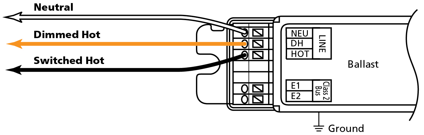
FIG. 2. The three-wire control method can enable many 120V or 277V dimming ballasts without compromising power line quality.
While
the adoption of 0–10V has really taken off in recent years due to the
proliferation of LEDs, there are many legacy 0–10V control systems
operating with fluorescent ballasts. These systems utilize four control
wires: two wires for providing switched power, and two additional
control wires for providing an analog voltage from 0 to 10V, which tells
the ballast the desired light level. Most dimming ballast manufacturers
have also made 0–10V ballasts, including Lutron (TVE ballasts),
Signify/Philips (Advance Mark 7 ballasts), and others.
As the
newest control protocol, digital control (EcoSystem or DALI — Digital
Addressable Lighting Interface) offers the highest dimming performance
and the greatest system flexibility. It is an excellent choice for
applications that need deep dimming as well as the ability to easily
make adjustments in response to changing building needs and take
greatest advantage of integration with other control systems. Buildings
with installed digital controls typically have the greatest interest in
maintaining control capabilities as part of a TLED upgrade.
Digitally-controlled ballasts utilize four
wires for power and control: a two-wire digital
communications bus (for example, E1
and E2 wires, often purple-colored) connected
to multiple ballasts (up to 64), and
Constant-Hot (unswitched) power on a separate
pair of line-voltage wires directly from
a circuit breaker panel (Fig. 3).
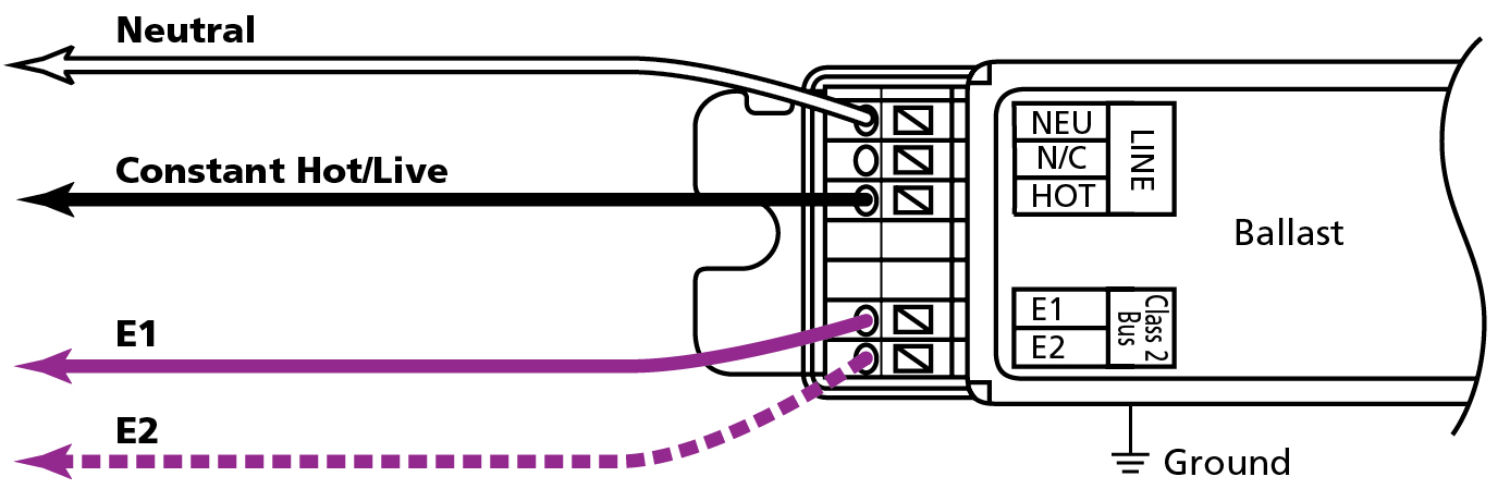
FIG.
3. Wiring for EcoSystem digital controls enables flexibility for
upgrades to add deeper dimming and intelligence features to building
lighting.
With most digital controls, power and
digital link can be run separately or in the same conduit, and the
wiring is topology free and polarity insensitive. Digital ballasts and
drivers are used to create flexible, digitally-controlled lighting
systems that are capable of being rezoned without any wiring changes and
allow dimming to light levels as low as 0.1% at the low end (Fig. 4).
Digitally-controlled ballasts are available from all major ballast
manufacturers.
Step 2: Understand the existing lamps and ballasts.
Once you have confirmed the existing control system, take stock of the
types of ballasts and lamps you have. There are a wide variety of
ballasts, lamp types, and lamp quantities in your fixtures. It’s often
easiest to start with the ballast label — this can help clarify the
control type the ballast supports and the expected dimming performance
(for example, is the low-end light level 10%, 5%, or 1%?). Low-end light
level is an important factor in how well the lighting meets the needs
of a given space or task. Conference rooms and training spaces often
require deep dimming, while atriums and public spaces may not.
To
upgrade fixtures to TLEDs, the ideal situation allows the existing
control system to remain untouched, the dimming performance to be
unaffected (or improved), and the existing quality and quantity of light
to be maintained (or increased). If the right TLED retrofit is chosen,
these goals can be reached; however, some adjustments to the internal
workings of the fixture may change. For example, a 3-lamp fluorescent
fixture may be able to be reduced to a 2-lamp TLED fixture, or a
multi-lamp fixture with one ballast may require two LED drivers.
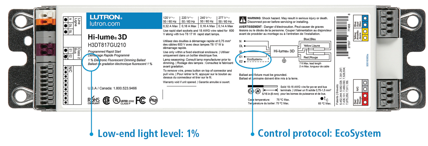
FIG. 4. An example ballast shows low-end light level and control type.
Choosing
the right LED driver is critical to ensuring compatibility with both
the existing control system and expected dimming performance. The driver
manufacturer’s website, online reference tools, application notes, and
whitepapers are useful references. Lutron, for example, recently published an application note
that helps identify characteristics of legacy installed ballasts,
provides expected performance information, and recommends a compatible
LED driver family to maintain performance and control compatibility.
(Note: The link will download a PDF.)
Retrofit UL Type C TLED
lamp and driver kits are available from multiple manufacturers, allowing
you to match the shapes and lengths of your existing fluorescent lamps,
as well as the control type in many cases. Purchasing the TLED upgrade
as a driver-plus-lamp kit ensures the driver and the lamp have been
tested together and are confirmed to be compatible. Work with the kit
manufacturer to ensure the replacement is suitable for your specific
installation, taking into consideration desired dimming performance,
control system compatibility, and even environmental conditions such as
temperature (especially in unusual applications such as gymnasiums or
other high-bay spaces).
For example, the Remphos brand from Light
Efficient Design offers a selection of TLED lamps for replacing
fluorescents, including T8, T5 HO, and T5 HE in most common lengths;
PLL/BIAX; and pin-based CFL with a variety of different driver options
and control types, including EcoSystem, 2-wire, and 3-wire controls. And
GE Lighting has a UL Type C TLED solution, available in T8 and T5 2-ft
(0.61 m) and 4-ft (1.22 m) lengths, multiple color temperatures, and
various lumen outputs. The lamps are compatible with a wide variety of
control types, including EcoSystem, 2-wire, and 3-wire controls.
Additional
manufacturers offer LED retrofit kits. These are solutions for
retrofitting existing fluorescent fixtures with LEDs using methods other
than TLEDs. LED retrofit kits may involve installing a subplate within
the fixture or employing other methods such as adhesive-backed light
strips. In some cases, such as when the current optics, aesthetics, or
mechanical characteristics of the fixture do not lend themselves to
effective TLED usage, it may make sense to completely replace the
existing fluorescent fixture with a new LED fixture. Examples of all
these solutions can be found at www.lutron.com/findafixture.
Step 3: Consider potential upgrades.
As part of an LED lighting upgrade, where each fixture will be modified
as part of the work, it’s worth considering whether the existing
lighting control system is up to the modern needs of the space. It may
make sense to perform a TLED lighting upgrade and to also retrofit the
existing wired control solution with a wirelessly-controlled system at
the same time in the following situations:
- When the control
type of the desired LED driver or TLED kit is not compatible with the
available existing electrical wiring or control system - When a
code compliance requirement for occupancy/vacancy sensors and/or
daylight sensors needs to be addressed, which cannot be accommodated by
the existing control system - When the needs of the space have
changed or outgrown the capabilities of the existing control system,
such as in a space that needs to be split into more granular control
zones
Prepare to go wireless
If you are considering a
wireless control upgrade, there are three methods for approaching it.
While all three require investment in a new control system, each can be
installed using existing electrical wiring while providing enhanced
system performance and communication with wireless fixture controls. The
result is better performance without all the cost of completely
replacing a wired system. Each example requires a Constant-Hot power
feed to the fixture; no additional wires need to be run.
Use a TLED kit with a digital driver and wireless control.
This option uses a digital driver (EcoSystem or DALI) controlled with a
wireless digital control mounted on a knockout on the outside of the
existing fixture. Installation requires access to the top or side of the
fixture or a nearby junction box to mount the control. A wireless
digital control solution adds flexibility and reduces risk by making it
easier to rezone and readdress fixtures using an app or centralized
control protocol as space usage changes over time.
Use a TLED kit with a 0–10V driver and control.
Option 2 allows a 0–10V LED driver to be controlled with a wireless
0–10V control that can be mounted on a knockout on the outside of the
fixture, and, like the digital solution, requires access to the top or
side of the fixture, or a nearby junction box. Dimming performance is
less predictable with 0–10V retrofits, but it is a good option for
meeting energy goals and providing elements of personal control to space
occupants. If existing 0–10V wires are present between fixtures for the
ballasts, this solution could also allow larger zones to be split into
smaller zones.
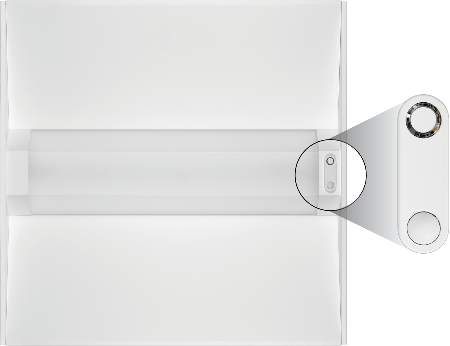
FIG. 5. Wireless TLED retrofit kit examples can include an OEM-installed, in-fixture wireless controller (zoomed inset).